Rear Axle / Hub Upgrade and Rear Brake Installation

Since July of 2009,I've been reading the 6-Pack forums, and the topic of rear axles / hubs has come up several times. Some of those threads have been rather heated regarding the design of the original parts, so I won't comment  :)  on the design other than to say rear axles have been known to break, and the outcome is not pretty. Here are two pixs of my original axles/hubs...note they use "U" joints.


Keeping with my "upgrade when possible" policy, I decided to replace both the hubs and axles with Good Parts "Axle and Hub Assembly with CV Joints".  They are not cheap, but 40 year old axles do suffer from metal fatigue, so why risk it.  Besides, Richard's parts are just plain gorgeous!


This is pretty much a direct bolt- in replacement for the stock parts, but you do need to check for clearance on the inside of the trailing arms.  In my case, there were casting ridges that needed to be smoothed off. A flap sander / drill combo made the job pretty easy. The driver's side T/A proved to be the problem , and I ended up pulling the axle/hub assembly out several times until enough material was removed to stop the axle boot from rubbing.


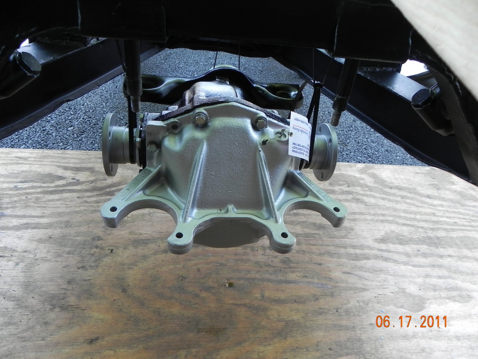
Because I'm using the stock differential, I needed an adapter plate to be bolted to the diff.....


One nice thing about doing these upgrades during a restoration is that I have easy access ,and I didn't need to pull off the trailing arms or differential like those folks who are working with the body still on the frame.

Bolts still need to be torqued, but the hub/axles fit, so let's get the rear brakes in place. 


Another small upgrade I've included is replacing the stock rear brake cylinders (top of pix) with "Morgan" cylinders that have a larger  7/8" bore for more rear stopping power.  I cleaned and reused the rear brake adjusters (bottom of pix) after 6-Pack member Brosky experienced a failure with new replacement parts. As usual, Brosky provided clear directions on how to clean and re-install the original adjuster. Thanks Paul !  


Following the Bently manual, plus some trial and error, I had the rear brakes assembled, so lets put them back on the trailing arm !


Slide the hub off, then slip the rear brake backing plate over the 6 studs, slide the hub back on, and secure with the nylock nuts. Torque to 16 lb ft. and we're looking good!


I painted the rear drums with a high heat paint from the folks at POR.  The drums appear to be in good shape with no wear ridges, so back on they go.


Note that the 22mm locking axle nuts require 250 lb ft of torque, so they will not be installed until the brake system is back in place and wifey can  press on the brake pedal while I use the torque wrench !  I'm using non-locking nuts just to keep things together during the restoration.


Another small segment put back together !


Trailing Arm Upgrade

I've mentioned before that I'm trying to include upgrades in this restoration, and the rear suspension was a bit of a weak sister as it came from the factory, so here is the first upgrade in this important area.


This is the problem area....5/16 steel studs screwed into aluminum, and torqued to only 16 lb ft max.  Rear wheels have been known to come off because of stripped threads....not good !


Bob Danielson (BobbyD) knew what was needed...steel Keenserts installed so the steel studs could get a real grip. This requires drilling out the old threads and using a tap to cut in new threads so the Keenserts can be installed.


The challenge was making a jig so the average guy could do this at home.  The six studs all have to be exactly perpendicular to the trailing arm, so the jig would need to be foolproof and precise. At this point Bob got Rick Patton involved. Rick is not only a TR6 guy, but he also runs a machine shop business, and he came up with a kit that allows even guys like me to perform this task !  Thanks Guys !!


A 1/2" thick piece of billet aluminum bolts to three existing studs...incredibly precise.


A drill alignment mandrel made out of hardened steel keeps the drill bit perpendicular...when I first put this together I thought of a fine Swiss watch, it's made to that degree of precision.


The drill bit is "X" size


A 7/16-14 bottoming tap


Here is what you need to get started.


Once the hole was drilled out, the tap work was easy..


Pull off the plate and screw in the Keenserts


A special tool comes with the Keenserts and is used to drive home the locking prongs.


Move the plate and repeat the process for the next three studs. Below, one side is done and ready for the new studs.


New studs with red loctite will ensure these bad boys will be good for the duration ! 


Here is the link to  Bobby D's site with more details....http://tr6.danielsonfamily.org/TAJig.htm


Time to put the "Pumpkin" back in place.

Those of you who have been following this blog may remember back to last November when Rhoda and I loaded up my differential, a.k.a the "pumpkin", and headed for TRF's C.A.R. shop in Armagh, PA., to drop it off for rebuilding. Tom Spadafora returned it a week later looking better than new !


Well, now it's time to put this bad boy back in the frame!  Now, I could have used my super strength to hold this 80 + lb chunk of  metal in place with one hand and install the nuts and washers with the other, but I promised the wife I wouldn't show off, so here is how it came together. :-)

I knew those extra heavy duty cable ties would come in handy some day...just keep inching the diff  into position. 
   Slow but sure.

A six- piece urethane mounting kit from TRF will help insure this process won't be repeated for a long time!


It does take a bit of fiddling / wiggling to get the mounts all in place so the nylock nuts can be installed


I couldn't resist adding a "before" pix of the differential and suspension !


Hey, it's time to quaff a root beer to toast getting a major piece of the drive train back in place !