Tillie Gets Her Eyes / Headlights !

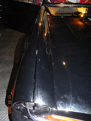
Before I start on the headlights, I want to bring closure to the previous blog concerning the fit of the TR6 hood (bonnet). Some of you may remember that I wasn't totally happy with the fit of the hood, especially the driver's side rear corner. I could not get that corner to be flush with the fender... it was about 2/16" high, no matter what I tried. A call to John my body guy was in order, since I knew he had the hood correct before taking it off for paint. We talked about the various adjustments I had tried, then he said, "Well, it needs to be twisted just a bit ,and here is how you do it".  I had visions of a pretzel-shaped hood and damaged paint, but I sucked it up and followed his instructions. I was amazed what a small piece of pine 2 X 4 wrapped in a rag, placed between the hood and the firewall, and some hand pressure could do! Gradually applying pressure to the high side "twisted" the hood enough so that the hood and fender are now flush without disturbing the rest of the fit !  The hood had been stored off the car for well over a year, and that must have caused the problem.
Thanks John !!


Ok, on to the headlamps. I couldn't install the headlights until the hood was done because the hood hinge bolts are in the area where the headlight buckets are installed.So,once the hood was complete, I was anxious to install and test the headlights. Tillie just didn't seem to have much personality without her "eyes".


The headlight wiring harness had been hanging loose for months, so part of the headlight "bucket" installation included threading the wires into the light housing and installing the 3 prong wire plug.


Once the bucket was in place, the light's adjusting housing was installed with two adjustment screws and attachment of the tension spring.


Now, Tillie is a special girl, so I want her to have "glamorous" eyes and provide me with with lots of light for night sorties. I went to head lamp guru Daniel Sterns' web site, Daniel Stern Lighting Consultancy , to see what he had to offer. Daniel doesn't have a "shopping cart", so he likes to have either a voice conversation or an email exchange to ensure you're buying the correct parts and to confirm your wire harness is up to the task. After a somewhat detailed email exchange,we decided on these 7" Cibie head lamps.


The H4 lamps are purchased separately and you can chose between 65/55 W -DOT legal bulbs or the" not quite legal" 70/65 W(or more) off- road- only bulbs!  


Bulb installation is very straight forward...open the clamp,remove the temporary plastic filler, install the bulb, and clamp it back in place.


Install the rubber boot and plug it in


A ring and 3 screws secure the lamp to the adjustment housing.


Ah, that looks better!
I won't put on the outer covering rings until spring when I can properly adjust the lights. Daniel Sterns has a very detailed "how to aim" section on his web site.

This is not my first experience with Cibie head lamps. Back in the last century, 1971 to be exact, I had a new '71 Pontiac Firebird on which I had installed the same type of lamps. The only problem I encountered was getting stopped by the police...not for doing anything illegal but to ask me questions about those awesome headlights!    


Tillie Has a Birthday !

Yup, it's true, the ole girl turned 40 on November 1st, 2013 !  According to my British Motor Heritage record, she rolled down the assembly line November 1, 1973. To mark this milestone, I thought a blog update was in order. I asked wife, Rhoda, to bake her a cake, and she asked if there should also be candles and singing! (I'm still waiting for the cake :-)) To add to the festivities, here is a look at what's been happening since my last post.

After my initial engine break-in run, I had a list of items to accomplish....after the oil / filter change, I re-torqued the head bolts and adjusted the valves.


I had several small coolant leaks that needed attention.  Most were just a matter of tightening clamps, however, I did have to pull off the water pump and WP housing after I discovered I'd used the wrong gasket sealant !


 Another small leak was where the coolant return line connects to the water pump housing....it's a compression fitting  that I hadn't tightend enough.


The triple ZS carbs required a bit of "tweaking", and I'm sure I'll need to do some more adjusting, but the engine does now idle, something it wasn't doing earlier.


Taking a break from the engine, I decided to install the glove box. Several 6-Pack forum searches made it clear that the box was a tight fit with the stock wiring harness, and as I'm using the AAW (Advance Auto Wire) kit with its thicker wiring, a modification was in order. Since this is not a daily driver, a big roomy glove box is not something I felt was necessary, so out came the saw....
This is the original cardboard type box, but I was amazed at how tough it was to cut!


Since guys usually can't get into a Jo-Ann Fabric and Craft Store with out a female escort :-), Rhoda took me there to purchase some canvas material to make a flexible  back section. It's not real pretty, but it is tough and will hold small miscellaneous papers, sunglasses, and a pair of string back driving gloves!


This flexible bag ,instead of the rigid box, will not cause any interference with the AAW wire harness.


Getting the gauges installed in the dash was a major milestone for me. Note that the cold air "eyeball vents" have been replaced with an additional gauge and a clock !

The oil temperature gauge is made here in the U.S. by Auto Meter. The angle ring makes it a bit easier to view.

An Auto Meter quartz clock gives the passenger something to monitor, and again the angle ring makes for easier viewing.


Once all the leaks were taken care, of I wanted to get the hood (bonnet) back on. Rhoda helped me get it out of the truck bed and onto the car with no paint damage, but I soon found out that was the easy part!

John, my body guy, told me to start with the hood high and forward  while first bolting on the hinges, then concentrate on making the hood square with the cowl next to the windshield. Next came getting the height adjusted at the front using the vertical adjustment of the hinges.  So far so good!


I used 6-Pack member Bobby D's method for mounting the hood latch....some grease on the plunger and tape on the latch to check alignment.

 A little adjustment on the plunger made it hit the tape dead center after this photo was taken.


Of course getting the hood release adjusted is critical, and since I'm not using the "prone to break" cable, my positive release lever installation was straight forward.


Ok ,you're thinking ,so what's the big deal about installing the hood...well ,gentle reader, getting the side gaps to look presentable consumed hours and hours of time!
 I called John, and he told me that the fenders needed to be adjusted in or out as needed to get an even gap once the hood was square with the cowl. There are approximately 12 bolts holding the fenders in place, and for the drivers side I needed to loosen all twelve, make my adjustment, tighten a few, close the hood, then repeat as needed.


The drivers side rear corner is still 1/16th inch high as I write this blog, and I don't know if it will ever be level...I've never battled so hard to achieve a 1/16th of an inch in my life :)! 

I originally hoped to drive Tille on her 40th birthday, but extra contracting work conspired against me, so it will be spring before I put her on the road. In the mean time, I'm enjoying the journey!

August 2013... Engine Break In Time !

It's been a long time coming, but I was able to perform the engine "break in run" on Aug. 16th.
Here is a five minute video clip with the details !


July 2013 and the wiring is finally done !!

It's been a long time since I started the TR6 wiring harness last September, but I can now say that  the Advance Auto Wire (AAW) harness is tested / finished, and I really feel good about this upgrade!

I spent quite a bit of time "fiddling" with the last foot of wiring at the dash- trying to make it as neat as possible by bundling all the wires going in the same direction and then cable tying the bundles and labeling the various wires.    
 I know this doesn't look nice and neat ,so let's call it organized confusion! 


I couldn't keep all of the various wire colors straight in my feeble mind :), so labels were used.


No matter how you bundle the wires, there has to be enough slack to reach to the various gauges.


The end result is wiring that doesn't jump out at you when the dash is pulled open.


I wasn't comfortable with the stock type "barrel" connectors, so I used "spade" type connectors with an insulator cover when possible.


Ok, see these little guys(below)...they clamp the Speedometer and Tachometer to the wood dash (two for each gauge).  Well ,guess what, I could find just two in my dash parts bag, not the four I needed. Since this is not something you will find at your local hardware, a call to Scott at Team Triumph produced the needed parts. What a great resource for obscure parts!


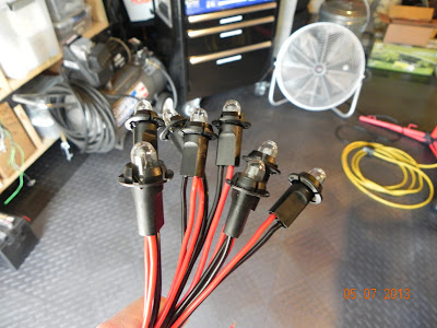
One of the things that slowed down this project was the lamps for the various gauges. I didn't want to re-use the old sockets, so I called Josh at British Wiring ,and he advised that the only replacements available were plastic two-wire sockets. I ordered enough for all the dash lamps.

 The down side is, "some assembly required".

My rusty soldering skills got a refresher course!

One down 15 more to go !

Hey ,that wasn't so bad!


The next issue was... how do I deal with all those red/black wires? Another look at the British Wiring web site revealed  various sizes of multi- connector blocks.

By looping the pins together, I had one point for power/ground.

During the middle of this process, a thread on the 6-Pack web site was posted concerning dash board wiring, and "Waytekwire" was mentioned as a vendor with a more streamlined connector.


Ok, I've got to add this caveat. The original "one wire" sockets (they get the ground through the metal teeth) are probably a better solution for the tach and speedo gauges (8 lamps). The plastic lamp sockets don't fit tight enough and tend to pop out while you're "fiddling" under the dash.  I spoke with Josh at British Wiring, and he hopes to get the older style in the future.


I also did some "custom" work on the dash, like moving the key back to the center console, adding a "push button" starter, and replacing the rheostat with a power outlet.


The aluminum plate with the toggle switches will eventually go where the radio would have normally been. It contains things like my hazzard switch/indicator, electric fan switch/indicator, and the overdrive controller indicator . (007 approved) :-)


Well, now that the wire harness is in place, it's time to start the engine!
Stay tuned!!

May 2013 Progress Report

May's pleasant weather and longer days have allowed me more opportunity to make progress on Tillie's  reconstruction. Those of you who have been following this blog may recall how last month I was so proud of myself getting the metal dash fascia and various pads installed...well ,one evening as I was admiring my handy work, it dawned on me that I didn't bolt in the windshield support brackets before installing the dash! A quick look confirmed my fears...getting those brackets bolted in with the dash already in place was going to be most difficult. Oh well, out came the dash and in went the brackets!
Right side


 Left side


As long as I'm going down this road, I may as well get the windshield frame bolted down and seated!


But before you bolt everything in place, make sure you have installed the vinyl covering that  goes over the inside of the windshield frame...especially the sides and bottom. I'll let you guess how I discovered this little item. Sigh!


Ok, here we are...back where I started but with the wind shield frame in place.


If there is one good thing about my "one step forward two steps backward" mode of restoration, it's the fact that I again start looking ahead for the next part to install before getting too far along. In this case, the steering column came to mind. I'm going to have many wires running right smack under the dash where the steering will be located...perhaps I need to get that column back in position! So, I get out the box labeled steering, lay everything out, and then panic when I realize I didn't take enough detailed photos of how the various parts go together!


Ok, calm down, first let's put  Art Lipp's Delrin bushings in the top and bottom of the upper column.
Going back and reviewing Bob Danielson's "how to" web page concerning these neat bushings, plus a steering column search of the 6-Pack web site,  gave me the confidence to move forward.


Getting the sequence of these spacers and washer took a bit of reading in Bentley's manual.


This looks correct !  If you're doing this project, consider a new rubber steering coupler. 


And now the top part of the column is in place and snugged down with new pieces of felt under the clamps. 


I'm always amazed at what the various vendors supply...in this case, TRF supplied felt of the correct thickness and size for the steering column clamps!


 I continue to work on wiring and I'm hoping by the end of next month to have the dash wiring in place and tested. Stay tuned.