Cunifer Brake Lines

The original brake lines on the TR6 were steel, and of course steel will rust.  Now most orignal Triumphs leaked enough oil, which got blown around the under side of the car, that rusting brake lines were not a huge issue, but my 40 year old brake lines had to be replaced.

 The Europeans have a lot of nasty weather, thus the need for a better brake line was a more urgent problem than in the U.S.  In the early 70's, the Swedish government decided  a rust proof replacement for steel was required.  Many studies were done, and the end result was cunifer....  a 90% copper / 10% nickel  alloy that won't rust like steel and won't crack like pure copper. Since that time, most high end European cars have switched to cunifer brake lines as standard equipment.

Austin Healey Wood is a company that normally deals with Austin Healey and Jaguar XK model restorations. Of course any restored Healey or Jag has cunifer brake lines, so the company makes up brakes lines for those cars and Triumphs and Porsche!  So again following my "upgrade when possible" philosophy, I ordered the cunifer brake lines for Tillie.

The lines come cut to the correct length, the connectors are in place, and the required flares have been made to each end.  They are shipped bent in gentle curves, so all the installer needs to do is bend the pipe to match the original.  Cunifer is soft enough that no special tools are required for bending...just match the new pipe up against the old and start bending with your hands !
The new cunifer lines come with an identification tag that tells you which old pipe it's replacing, and I did label the old pipes as I removed them, so bending the new was an enjoyable project ! 


Oh, did I mention that cunifer will polish up really nice!  I know, who will see polished brake lines?


As long as I'm going over the top on non-essential details, how about painting the clips that hold the brake line in place... red !


The solid brass "T" connectors also polished up nicely, and a little clear coat should keep them looking good ! 


And finally, I decided to add polyester braided sleeves to the exposed lines for a bit of protection against rocks, etc.  They are split, so removal would not be a problem.

Time To Tackle The Body

Well, now that I have a rolling chassis, I have to confront the body tub and various panels.  I've been putting this off for almost two years because I don't have the skill set to do it myself, and I know a good body man and painter cost serious money. Here is my body tub....not too pretty


Don't you wonder what's under this mess !?! 


Back in the winter of '09 / '10, I pulled off the front fenders and used a heat gun and scrapper to clean off the worst of the gunk.


I never got to the rear fenders, so I'll be paying to have them cleaned.


A highly recommended media blaster has been located less than a hour away, so it's time to load up a U-Haul and get the body show on the road !


Trying to figure out how to load all the various parts / pieces so they will travel without tearing themselves apart proved to be quite a job.  My neighbor Tom, who is a retired fire chief, came over and worked his magic on the ropes where needed.


 Good old ratchet straps work wonders.

Stay tuned for more car body fun !

We Have a Roller !

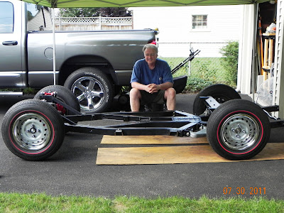
I think the last time tires were on Tillie was December 2009, so it was with great expectations that I mounted 4 wheels/tires on to the chassis creating a "roller"...no brakes, no power, no steering, but it does roll !


Yeah, I'm one happy camper !  Now it's time to get busy with brake and fuel lines. 


Anti- Sway Bars

  The '68 TR250, even though it had the new 6 cylinder engine, didn't come from the factory with  an anti-sway bar, and it soon became apparent that the heavier engine was causing excessive understeer and would require some attention to the suspension. The factory decided a front 3/4" anti-sway bar would cure the understeer problem, and life would be good. So, front anti-sway bars were  introduced first on the '69 TR6s. Actually, the factory was a little late to the anti-sway bar party. Several aftermarket companies were already providing bars for the earlier model TRs.  FYI, understeer is what happens when you turn the steering wheel on a wet road, but the car continues to go straight.  Well, the bar helped, but the TR6 still wanted to understeer. Of course the racing folks soon figured out that a larger front anti-sway bar helped even more, and a matching rear anti-sway bar brought about the neutral steering the racers desired.
Keeping in mind that a stock U.S. spec. TR6 only produces about 104 hp, it's pretty obvious that these cars aren't made for straight line drag racing. No, it's a sports car, made to go around curves quickly! With that thought in mind, I ordered new matching 7/8" front and rear anti-sway bars from Good  Parts. Richard has a race prepped TR6, so he knows how to make these cars handle.


The bars are power coated in semi-gloss black.


The mounting brackets are carved out of solid billet aluminum and use nylatron bushings. 


All the hardware is first class !


Since the TR6 came from the factory with provisions for a front anti-sway bar, the new Good Parts bar is a bolt on affair.


Front bar all buttoned up !


Well, it's on to the rear anti-sway bar, and since the factory did not provide for such a bar, I'll need to break out the cordless drill, a 7/16th" bit, and put 4 holes in the frame ! Wish me luck!


Using the old measure twice and drill once rule, I was able to get 2 holes on each side of the frame in the correct place !  A "U" bolt is fed up, across, and down, and will be used to hold a bracket on each side of the frame.


Another bracket is mounted up against the trailing arm, directly under the rear spring on each side.


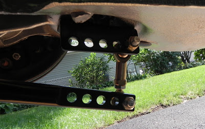
The end result looks like this on each side.  The extra holes allow for future adjustment.


As usual, with Good Parts, the brackets are cut from billet aluminum and the bushings are nylatron !

Rear Axle / Hub Upgrade and Rear Brake Installation

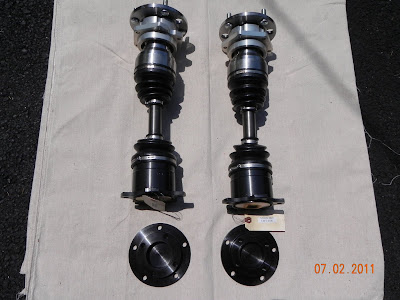
Since July of 2009,I've been reading the 6-Pack forums, and the topic of rear axles / hubs has come up several times. Some of those threads have been rather heated regarding the design of the original parts, so I won't comment  :)  on the design other than to say rear axles have been known to break, and the outcome is not pretty. Here are two pixs of my original axles/hubs...note they use "U" joints.


Keeping with my "upgrade when possible" policy, I decided to replace both the hubs and axles with Good Parts "Axle and Hub Assembly with CV Joints".  They are not cheap, but 40 year old axles do suffer from metal fatigue, so why risk it.  Besides, Richard's parts are just plain gorgeous!


This is pretty much a direct bolt- in replacement for the stock parts, but you do need to check for clearance on the inside of the trailing arms.  In my case, there were casting ridges that needed to be smoothed off. A flap sander / drill combo made the job pretty easy. The driver's side T/A proved to be the problem , and I ended up pulling the axle/hub assembly out several times until enough material was removed to stop the axle boot from rubbing.


Because I'm using the stock differential, I needed an adapter plate to be bolted to the diff.....


One nice thing about doing these upgrades during a restoration is that I have easy access ,and I didn't need to pull off the trailing arms or differential like those folks who are working with the body still on the frame.

Bolts still need to be torqued, but the hub/axles fit, so let's get the rear brakes in place. 


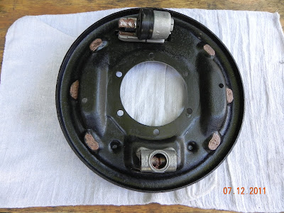
Another small upgrade I've included is replacing the stock rear brake cylinders (top of pix) with "Morgan" cylinders that have a larger  7/8" bore for more rear stopping power.  I cleaned and reused the rear brake adjusters (bottom of pix) after 6-Pack member Brosky experienced a failure with new replacement parts. As usual, Brosky provided clear directions on how to clean and re-install the original adjuster. Thanks Paul !  


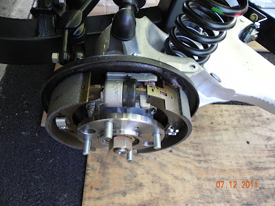
Following the Bently manual, plus some trial and error, I had the rear brakes assembled, so lets put them back on the trailing arm !


Slide the hub off, then slip the rear brake backing plate over the 6 studs, slide the hub back on, and secure with the nylock nuts. Torque to 16 lb ft. and we're looking good!


I painted the rear drums with a high heat paint from the folks at POR.  The drums appear to be in good shape with no wear ridges, so back on they go.


Note that the 22mm locking axle nuts require 250 lb ft of torque, so they will not be installed until the brake system is back in place and wifey can  press on the brake pedal while I use the torque wrench !  I'm using non-locking nuts just to keep things together during the restoration.


Another small segment put back together !


Trailing Arm Upgrade

I've mentioned before that I'm trying to include upgrades in this restoration, and the rear suspension was a bit of a weak sister as it came from the factory, so here is the first upgrade in this important area.


This is the problem area....5/16 steel studs screwed into aluminum, and torqued to only 16 lb ft max.  Rear wheels have been known to come off because of stripped threads....not good !


Bob Danielson (BobbyD) knew what was needed...steel Keenserts installed so the steel studs could get a real grip. This requires drilling out the old threads and using a tap to cut in new threads so the Keenserts can be installed.


The challenge was making a jig so the average guy could do this at home.  The six studs all have to be exactly perpendicular to the trailing arm, so the jig would need to be foolproof and precise. At this point Bob got Rick Patton involved. Rick is not only a TR6 guy, but he also runs a machine shop business, and he came up with a kit that allows even guys like me to perform this task !  Thanks Guys !!


A 1/2" thick piece of billet aluminum bolts to three existing studs...incredibly precise.


A drill alignment mandrel made out of hardened steel keeps the drill bit perpendicular...when I first put this together I thought of a fine Swiss watch, it's made to that degree of precision.


The drill bit is "X" size


A 7/16-14 bottoming tap


Here is what you need to get started.


Once the hole was drilled out, the tap work was easy..


Pull off the plate and screw in the Keenserts


A special tool comes with the Keenserts and is used to drive home the locking prongs.


Move the plate and repeat the process for the next three studs. Below, one side is done and ready for the new studs.


New studs with red loctite will ensure these bad boys will be good for the duration ! 


Here is the link to  Bobby D's site with more details....http://tr6.danielsonfamily.org/TAJig.htm